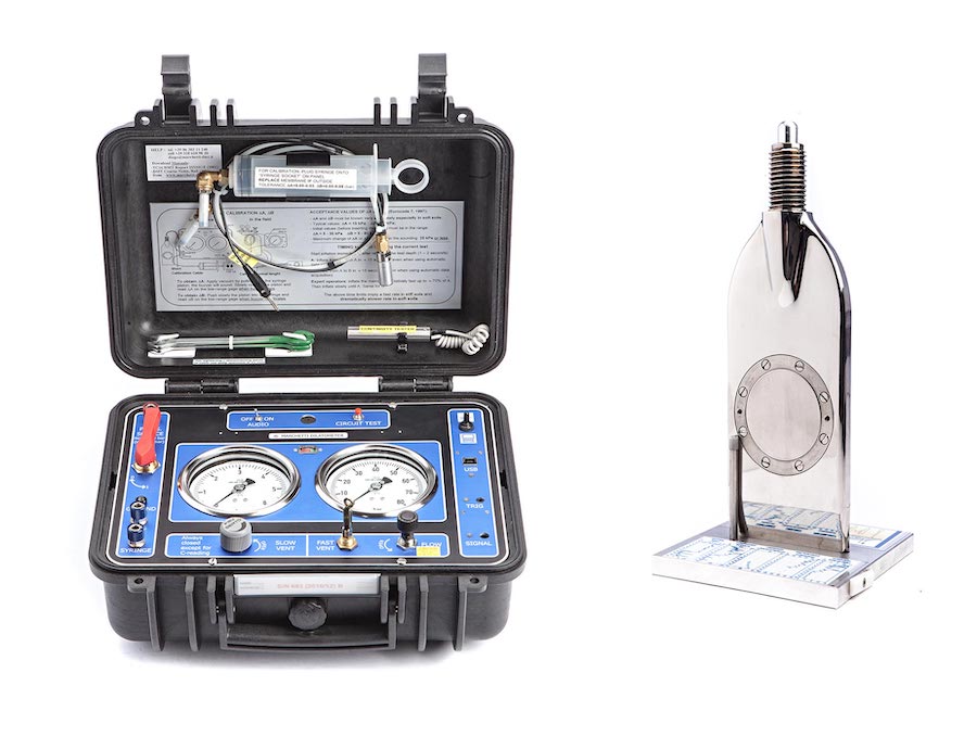
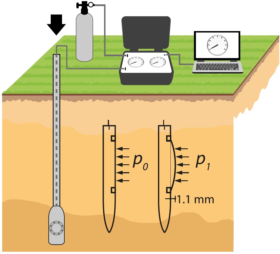
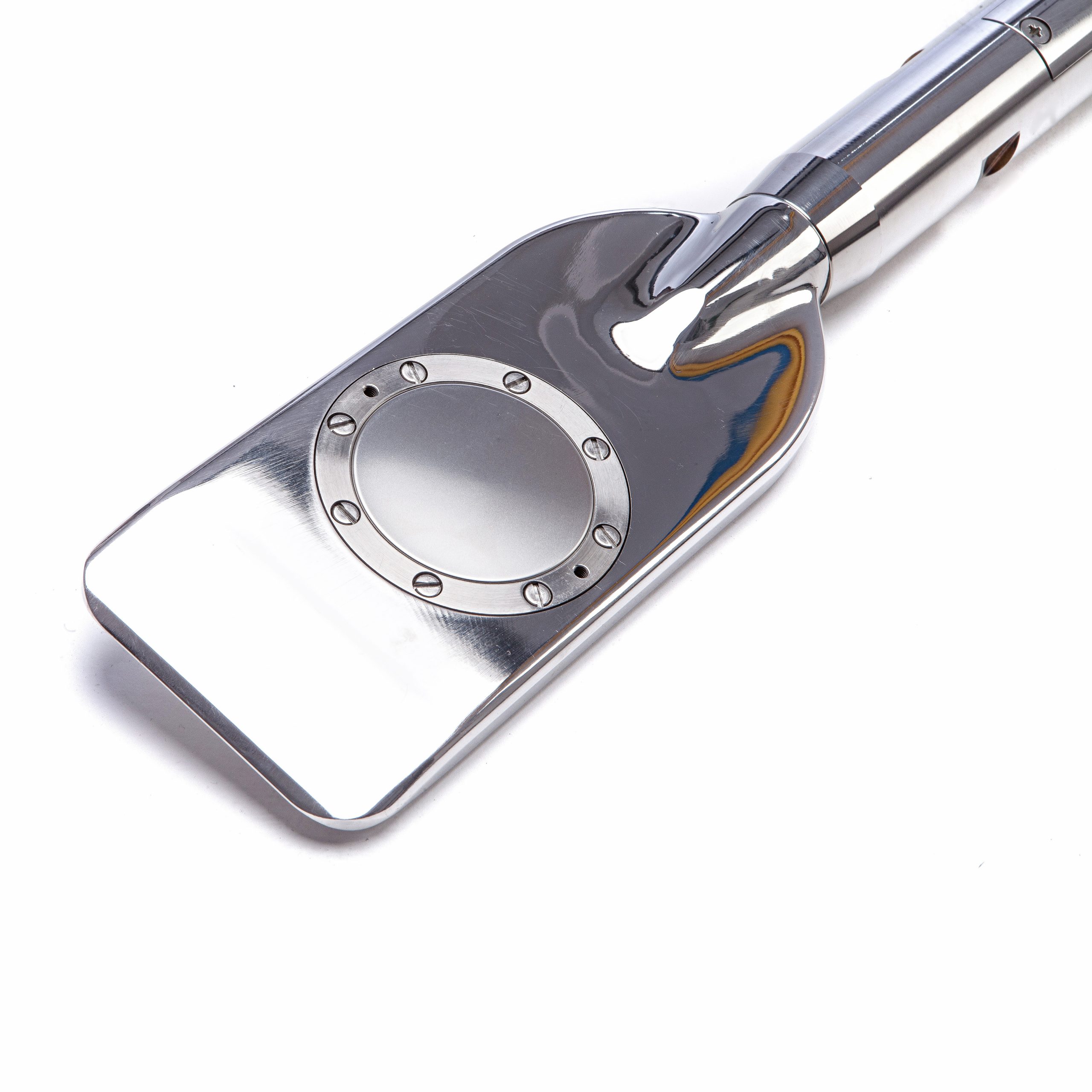
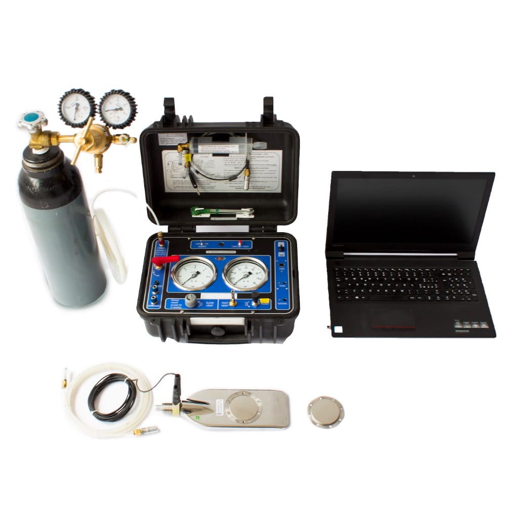
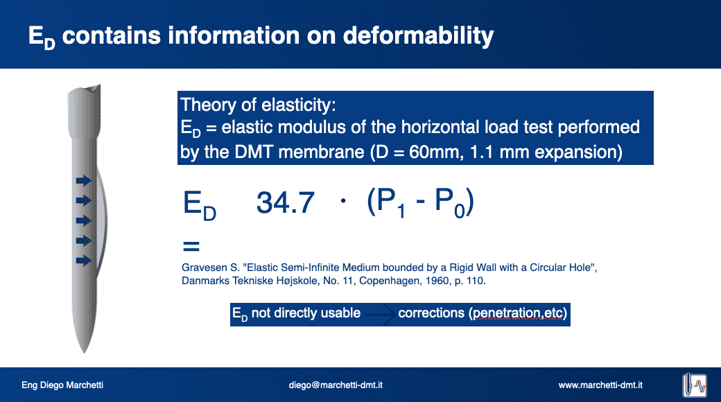
The valves on the control unit panel permit to control the gas flow to the blade and to deflate the system. The main valve provides a positive shutoff between the gas source and the control unit-blade system. The micrometer flow valve is used to control the pressurization rate during the test. The toggle vent valve allows the operator to vent quickly the system pressure to the atmosphere. The slow vent valve allows a slow deflation, in order to take the C-reading.
The general layout of the dilatometer test is shown in Fig. 1 and Fig. 4. The test starts by inserting the dilatometer into the ground. Immediately after the penetration the operator starts inflating the membrane and takes, in ≈ 15 seconds from stopping the penetration, the A-pressure. Then he continues the inflation and takes B in additional ≈ 15 seconds.
- the A-pressure is the pressure required to just begin to move the membrane against the soil (“lift-off”);
- the B-pressure is the pressure required to move the center of the membrane 1.1 mm against the soil;
- A third reading-C (“closing pressure”) can also optionally be taken by slowly deflating the membrane soon after B, using the slow vent valve, in about 30 seconds, in order to obtain the pre-insertion pore water pressure.
The blade is then advanced into the ground of one depth increment (typically 20 cm) and the procedure for taking A, B readings is repeated at each depth.
The pressure readings A, B must then be corrected by the values DA, DB determined by calibration, to take into account the membrane stiffness, and converted into p0, p1 subsequently used in the interpretations of the results.
The readings acquisition can be mechanical or automatic by connecting the control unit to the computer and using the SDMTElab Software.
Dissipation Tests are also possible to get estimates of the Consolidation and Permeability Coefficient (Totani et al. 1998).