A Flat Dilatometer test consists in advancing a blade into the ground with any common field machine. At each test depth, a circular steel membrane located on one side of the blade is expanded horizontally against the soil. The pressure readings are recorded at specific moments during the membrane expansion. The blade is then advanced to the next test depth, typically with 0.20 m depth interval.
DMT
Detailed Description
Checks on the DMT equipment
Covering maintenance, checks and various operative aspects
Inserting DMT
Brief Description
Research DMT
DMT Earth Pressure Cells
Flat dilatometer composition
With reference to Fig. 1 (DMT Test Layout): The blade is connected to a control unit on the ground surface by a pneumatic-electrical cable running through the insertion rods and transmitting gas pressure and electrical continuity.
The blade has a cutting edge to penetrate the soil and it is advanced into the ground using common field equipment, i.e. push rigs normally used for the cone penetration test (CPT) or drill rigs. Push rods are used to transfer the thrust from the insertion rig to the blade. Advancing the blade by percussion, e.g. using the SPT hammer, is also possible. Dynamic insertion is not the preferred way, but in some countries driving is the most common insertion method.
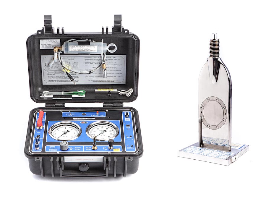
The pressure required to expand the membrane is provided by a gas tank (n.5), generally nitrogen or compressed air, connected to the control unit by a pneumatic cable. The gas tank, is equipped with a pressure regulator (suitable to gas type) which must be able to supply a regulated output pressure of at least 7-8 MPa.
The control unit is equipped with pressure gage(s), an audio-visual signal and vent valves and two pressure gages, connected in parallel, that have different scale ranges: a low-range gage (1 MPa), self-excluding when the end of the scale is reached, and a high-range gage (8 MPa). The low-range gage permits high resolution when the pression readings are small.
The valves on the control unit panel permit to control the gas flow to the blade and to deflate the system. The main valve provides a positive shutoff between the gas source and the control unit-blade system. The micrometer flow valve is used to control the pressurization rate during the test. The toggle vent valve allows the operator to vent quickly the system pressure to the atmosphere. The slow vent valve allows a slow deflation, in order to take the C-reading.
The general layout of the dilatometer test is shown in Fig. 1 and Fig. 4. The test starts by inserting the dilatometer into the ground. Immediately after the penetration the operator starts inflating the membrane and takes, in ≈ 15 seconds from stopping the penetration, the A-pressure. Then he continues the inflation and takes B in additional ≈ 15 seconds.
- the A-pressure is the pressure required to just begin to move the membrane against the soil (“lift-off”);
- the B-pressure is the pressure required to move the center of the membrane 1.1 mm against the soil;
- A third reading-C (“closing pressure”) can also optionally be taken by slowly deflating the membrane soon after B, using the slow vent valve, in about 30 seconds, in order to obtain the pre-insertion pore water pressure.
The blade is then advanced into the ground of one depth increment (typically 20 cm) and the procedure for taking A, B readings is repeated at each depth.
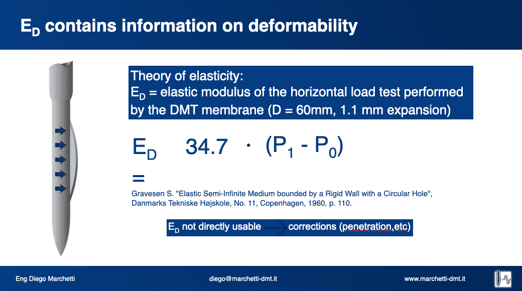
The pressure readings A, B must then be corrected by the values DA, DB determined by calibration, to take into account the membrane stiffness, and converted into p0, p1 subsequently used in the interpretations of the results.
The readings acquisition can be mechanical or automatic by connecting the control unit to the computer and using the SDMTElab Software.
Dissipation Tests are also possible to get estimates of the Consolidation and Permeability Coefficient (Totani et al. 1998).
Executing DMT
- DMT Testing Procedure
- C-Reading
- Checks For Quality Control
- Dissipations
- Inflation Speed
- Niche Silts
- Semiliquid Soils
- Fields Form for writing data
A description covering maintenance, checks and various operative aspects, i.e. a kind of user manual, can be found in the Marchetti 2001 Bali Course maintenance. If the soil is “semiliquid” or is possibly a “niche silt”, please refer to the corresponding headings below.
A brief description is also in the DMT specifications.
The C-reading is particularly useful in granular soils, where it permits to know the equilibrium pore pressure. In practice it replaces, in sand, a piezometer.
See TC16 DMT Report or C-reading
Checks for quality control
As to maintenance
TC16 DMT Report
The test starts by inserting the dilatometer into the ground. Immediately after the penetration the operator starts inflating the membrane and takes, in » 15 seconds from stopping the penetration, the A-pressure. Then he continues the inflation and takes B in additional » 15 seconds.
Short (2 min) dissipations are executed in silts to find out if they are “niche silts” i.e. silts where there is appreciable drainage during the duration of the test (» 0.5 min).
As noted by Robertson and Campanella (1986) “the DMT is extremely simple to operate and to maintain”, while, according to ASTM D 6635 “DMT results are exceptionally reproducible and operator insensitive”. However, when testing semiliquid soils, if highly accurate results have to be obtained, the test procedure must be followed scrupulously. Small errors, unimportant in medium to hard soils, become important when the readings are small. It is advisable to have the tests executed by an operator already familiar with DMT.
A detailed treatment of the topic can be found in “DMT execution in semiliquid soils” that provides recommendations concerning the DMT execution in semiliquid soils, where maximum scrupulosity is necessary to obtain accurate results. Small errors, unimportant in medium to hard soils, become important when the readings are small.
Field forms for writing the data, in case data are not taken automatically.
Main Applications
Soil Parameters
DMT provides estimates of the oedometer modulus M, shear strength Su, OCR and Ko in clay, liquefaction resistance CRR.
Read MoreCompaction Control
DMT has been recognized to be twice more sensitive than CPT to compaction. Before-after DMTs are increasingly used to monitor not only the gain in modulus but also the gain in OCR due to compaction.
Read MoreLiquefaction
A just published Asce paper (2016) provides an updated KD-CRR correlation for estimating the liquefaction resistance CRR from KD. The paper also includes a chart for estimating CRR based at the same time on CPT and DMT.
Read MoreG-Gamma Decay Curves
SDMT provides the small strain modulus Go and the working strain modulus MDMT, i.e. two points of the G-γ curve. The availability of two points is helpful while selecting the design G-γ curve.
Read MoreSettlement Prediction
Many world experts consider DMT one of the best tools for predicting settlements.
Read MoreDetecting Slip Surfaces in Clay Slopes
Values of the DMT parameter KD = 2 found in a slope signal the presence of slip surfaces, active or quiescent.
Read MoreStress History Information
The DMT parameter KD is considerably more sensitive to Stress History than other in situ tools. Stress history is important, as it significantly increases moduli and liquefaction resistance. If Stress History is not felt, its benefits are wasted, leading to an uneconomical design.
Read MoreLaterally Loaded Piles
DMT was originally conceived to provide estimates of the horizontal soil modulus for laterally loaded piles.
Read More